Industrial Device Programming Services
Delivering Industrial Automation Programming: ASR-Engineering’s Approach
At ASR-Engineering, our approach to providing industrial automation programming services is both dynamic and meticulous, aimed at ensuring a seamless integration and optimal performance of your automation system. Through a series of well-defined steps, we work closely with you to deliver tailored solutions that meet your specific needs.
1. Consultation and Assessment: Understanding Your Goals
We initiate the process by engaging in a comprehensive consultation where we actively listen to your automation requirements and goals. Our experienced team conducts a thorough assessment of your existing systems, if any, to gain a deep understanding of your unique needs.
2. System Design and Integration: Crafting a Cohesive Solution
Building upon the assessment, we proceed to design a comprehensive automation system. This involves the careful selection of suitable robotic components, HMI interfaces, and PLC solutions. Our focus remains on achieving compatibility and seamless integration among these crucial components.
3. Robotic Programming: Precision and Efficiency
Our skilled engineers then embark on programming industrial robots to execute tasks with precision and efficiency. Through defining precise motion paths, trajectories, and end-effector operations, we optimize the performance of the robots in your automation setup.
4. HMI Development: Empowering Interaction
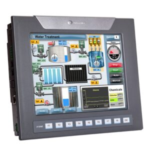
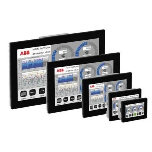
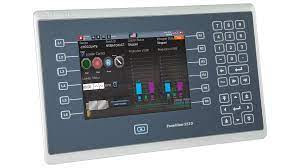
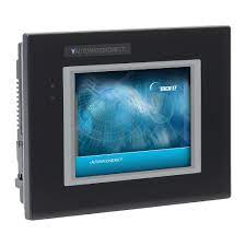
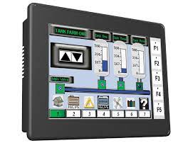
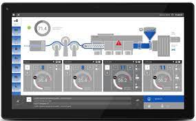
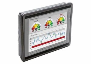
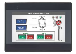
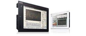
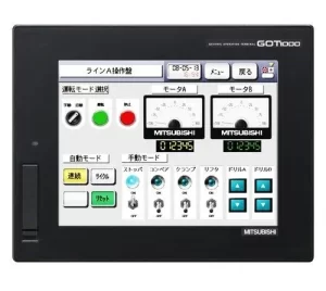
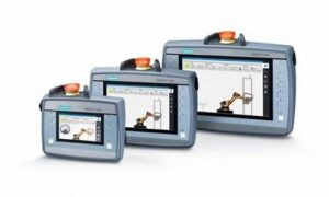
Creating user-friendly Human Machine Interfaces (HMIs) is a cornerstone of our approach. We design HMIs that facilitate effortless interaction with the automation system. Real-time data display and system status updates empower operators and supervisors to make well-informed decisions. Furthermore, we ensure provisions for manual interventions when necessary.
5. PLC Programming: Mastering Control
ASR-Engineering takes charge of programming the Programmable Logic Controllers (PLCs) that govern the entire automation process. This entails crafting intricate logic, defining inputs and outputs, implementing stringent safety protocols, and ensuring smooth communication between robots and HMIs.
6. Testing and Commissioning: Ensuring Excellence
Prior to deployment, we subject the entire system to rigorous testing. This meticulous process identifies any potential issues and ensures that the system meets performance and safety standards. Upon successful testing, we expertly commission the system for optimal functionality.
7. Training and Support: Empowering Your Team
Our involvement extends beyond installation. We provide comprehensive training to your staff on operating and maintaining the automated system. Additionally, ASR-Engineering offers ongoing support and maintenance services to ensure the system’s continuous operation at its best.
8. Continuous Improvement: Enhancing Efficiency
We recognize the value of continuous enhancement in automation systems. Collaboratively, we work with you to gather feedback and identify areas for improvement. By implementing updates and upgrades, we consistently elevate the efficiency and performance of your automation setup.
Through this comprehensive and client-centric approach, ASR-Engineering ensures that your industrial automation programming needs are met with precision, excellence, and an unwavering commitment to driving your operational success.
For more information about our programming services, please click on the tabs below. We look forward to assisting you in achieving your automation goals.
Industrial Robotics Engineering
ABB Robots
Engineering Functions Supported
Robot Types Supported
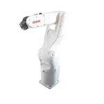
Denso Robots
Engineering Functions Supported
Robot Types Supported
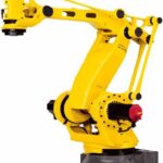
Fanuc Robots
Engineering Functions Supported
Robot Types Supported
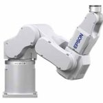
Epsom Robots
Engineering Functions Supported
Robot Types Supported
Omron Robots
Engineering Functions Supported
Robot Types Supported
Kawasaki Robots
Engineering Functions Supported
Robot Types Supported
Kuka Robots
Engineering Functions Supported
Robot Types Supported
Yaskawa Robots
Engineering Functions Supported
Robot Types Supported
Robotic Integration & Engineering Details
Integrating PLC to Robot
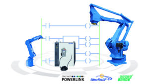
Integrating a robot into a PLC (Programmable Logic Controller) may present various complexities due to the need for seamless communication and synchronization between these two distinct systems. First, there might be differences in communication protocols and interfaces, requiring careful configuration and compatibility considerations. Additionally, the robot’s motion control and safety features need to be harmonized with the PLC’s logic and decision-making processes to ensure safe and efficient operation. Furthermore, programming the robot’s actions within the PLC’s environment may demand specialized knowledge of both robotic programming languages and PLC programming languages, adding another layer of complexity. Robust testing and troubleshooting procedures become essential to identify and resolve potential issues arising from this integration. Overall, successful integration demands a comprehensive understanding of both robotics and PLC systems, meticulous planning, and diligent testing to achieve a functional and reliable automated solution.
Solving the Challenge
ASR – Engineering, solves the challenges in integrating a robot into a PLC through a combination of technical expertise and careful planning. Here are some of the ways they address the complexities mentioned in the paragraph:
- Communication Protocols and Interfaces: research and analyze the communication requirements of both the robot and the PLC. They work on configuring the appropriate protocols and interfaces to ensure seamless data exchange between the two systems.
- Motion Control and Safety Integration: collaborate with robotics experts and PLC programmers to align the robot’s motion control and safety features with the logic and decision-making processes of the PLC. They implement safety measures to prevent collisions or hazardous situations during operation.
- Programming Knowledge: possess a deep understanding of both robotic programming languages and PLC programming languages. They leverage this expertise to write code that enables the robot to function within the PLC’s environment smoothly.
- Testing and Troubleshooting: conduct rigorous testing of the integrated system to identify any potential issues. They employ various testing scenarios to ensure the robot and PLC work together flawlessly. If problems arise, they use their troubleshooting skills to find and resolve issues promptly.
- Comprehensive Understanding: have a holistic understanding of robotics and PLC systems, allowing them to envision how these components interact within the larger automation system. This knowledge enables them to plan and execute the integration effectively.
- Meticulous Planning: plan each step of the integration process carefully. They consider all the technical aspects, dependencies, and potential challenges to create a well-structured integration plan.
- Diligent Testing: conduct extensive testing at various stages of the integration to verify that the robot and PLC work harmoniously. They conduct real-world simulations and evaluate performance to ensure the automated solution functions reliably.
By employing technical skills, thorough planning, and attention to detail, ASR – Engineering successfully overcomes the complexities of integrating a robot into a PLC, resulting in a functional and reliable automated system.
Robot Cells
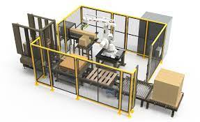
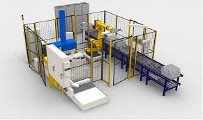
A robot work cell is a self-contained and automated area within an industrial setting where robots, machinery, and equipment work collaboratively to perform specific tasks or manufacturing processes. It is designed to streamline and optimize production by integrating various components to create a cohesive and efficient workflow. Here’s a description of a typical robot work cell:
Components of a Robot Work Cell:
- Robots: The work cell includes one or more industrial robots that are specialized in performing specific tasks. These robots are equipped with end effectors or tools tailored to the work cell’s requirements.
- Machinery and Equipment: In addition to robots, the work cell may incorporate various machines and equipment, such as conveyor belts, CNC machines, or automated material handling systems, to support the production process.
- Sensors and Vision Systems: Work cells often feature sensors and vision systems that provide real-time data and feedback to the robots and control systems. These sensors help in detecting objects, monitoring quality, and ensuring safety.
- PLC (Programmable Logic Controller): A PLC acts as the brain of the work cell, controlling and coordinating the movements and interactions between robots and other equipment. It manages the workflow and ensures synchronization among all components.
- HMI (Human-Machine Interface): The HMI serves as the interface between human operators and the work cell. It provides a user-friendly way for operators to monitor the process, make adjustments, and receive important information.
Working Process: The robot work cell operates based on a predefined sequence of tasks, which can include material handling, assembly, welding, painting, or any other manufacturing process. The process typically involves the following steps:
- Input: Raw materials or components enter the work cell, either manually or through automated material handling systems.
- Task Execution: The robots and machinery within the cell work collaboratively to perform the designated tasks. Robots may pick and place objects, perform precise movements, or carry out specific operations.
- Quality Control: Vision systems and sensors check for defects or deviations from the desired specifications. Any inconsistencies may trigger corrective actions.
- Output: The finished products or processed components exit the work cell, ready for further assembly or packaging.
Benefits of a Robot Work Cell:
- Increased Productivity: By automating repetitive and labor-intensive tasks, work cells can significantly boost production efficiency and output.
- Improved Quality: Robots and vision systems ensure consistent and precise manufacturing, leading to higher product quality and fewer defects.
- Enhanced Safety: By delegating hazardous tasks to robots, work cells help create a safer working environment for human operators.
- Flexibility: Work cells can be reprogrammed and reconfigured for different tasks, making them adaptable to changing production needs.
- Cost Savings: Despite the initial investment, work cells often result in long-term cost savings due to increased productivity and reduced labor expenses.
Robot work cells play a crucial role in modern manufacturing, driving industries towards greater automation, efficiency, and competitiveness.
Requirement Gathering: To begin with, we will start by understanding your production requirements, goals, and specific tasks you want to automate. We will work closely with you, collaborating to gather all necessary information about the production process and desired outcomes.
Conceptual Design: With the gathered requirements in mind, we will proceed to develop a conceptual design for the robot work cell. This entails determining the number and type of robots needed, selecting appropriate machinery and equipment, and meticulously planning the overall layout of the work cell.
Robot Selection: Careful evaluation of different robot models will be undertaken by ASR Engineering, aligning with the work cell’s requirements. We will thoughtfully consider factors such as payload capacity, reach, speed, accuracy, and the specific tasks the robots will perform.
Machinery and Equipment Integration: The team at ASR Engineering then identifies the supporting machinery and equipment required for the work cell. We will ensure compatibility and seamless integration between robots, conveyors, CNC machines, vision systems, sensors, and other essential components.
PLC and HMI Programming: As the next step, ASR Engineering then develops PLC and HMI programs that serve as the brain of the work cell. The PLC takes charge of controlling the overall workflow, robot movements, and coordination with other equipment. The HMI provides an intuitive interface for operators to interact with and monitor the work cell effectively.
Robot Programming and Calibration: ASR – Engineering then proceeds to program the robots with precision, enabling them to perform their designated tasks accurately and efficiently. They also meticulously calibrate the robots to ensure precise movements and alignments within the work cell.
Safety Integration: Safety remains a critical aspect of robot work cells and ASR – Engineering is committed to incorporating essential safety features. This includes safety fences, light curtains, and emergency stop systems to protect human operators and ensure safe operation.
Testing and Optimization: Prior to deployment, ASR – Engineering will conduct thorough testing of the robot work cell. The objective is to identify and resolve any potential issues. We will work diligently to optimize the work cell’s performance, accuracy, and cycle times, achieving the desired level of productivity.
Installation and Commissioning: Taking the lead in ensuring a seamless on-site installation, ASR – Engineering meticulously handles the deployment of the robot work cell. We diligently commission the system, fine-tune its parameters, and conduct comprehensive performance tests to ensure everything functions flawlessly.
Training and Support: ASR – Engineering takes the responsibility of providing comprehensive training to the client’s operators and maintenance staff. This training familiarizes your team with the operation and maintenance of the robot work cell. In addition, ASR – Engineering offers ongoing support and maintenance services to ensure the work cell runs efficiently over time.
Continuous Improvement: Acknowledging the potential for continuous enhancement, ASR – Engineering maintains a close working relationship with you our client. We actively gather feedback and identify opportunities for improvement. In response, we implement updates, upgrades, and optimizations to enhance the work cell’s performance and adapt it to changing production needs.
It’s important to note that the engineering process may vary based on the complexity of the work cell, the specific industry, and the unique requirements of each client. If you are interested in ASR -Engineering’s services, I recommend contacting our sales staff and schedule an appointment
End Effectors
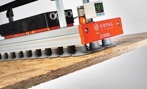
Robot end effectors, also known as robot grippers or robot hands, are essential components that enable robots to interact with their environment. These devices serve as the “hands” of the robot, allowing them to grasp, hold, and manipulate objects. Transitioning from one task to another seamlessly, end effectors are designed for versatility, making them adaptable to various applications. They play a vital role in industries like manufacturing, warehousing, and assembly, where robots need to handle diverse objects with precision and efficiency. With a wide range of end effectors available, including suction cups, claws, and magnetic grippers, robots can easily switch between tasks and perform their duties with enhanced dexterity and effectiveness.
One size robot end effector does not fit all applications due to the following reasons:
- Diverse Object Shapes and Sizes: Different applications involve handling objects with various shapes, sizes, and weights. A single-size end effector may not have the flexibility to securely grip and manipulate objects of different dimensions.
- Specific Gripping Requirements: Some tasks may require delicate handling, while others demand a firm grip. Custom end effectors can be designed with specific gripping mechanisms like vacuum suction cups, soft fingers, or mechanical clamps to suit each application’s unique needs.
- Material Compatibility: The type of material being handled can impact the end effector’s design. For instance, handling fragile objects might require a soft and non-marking end effector, while robust materials may necessitate a more rigid and durable grip.
- Environmental Constraints: Different work environments may present challenges such as high temperatures, moisture, or contamination. Custom end effectors can be tailored to withstand these conditions, ensuring optimal performance and durability.
- Automation Complexity: Some applications may involve complex automation tasks, where a single-size end effector might not have the required capabilities or degrees of freedom to execute intricate movements.
- Safety Considerations: Safety is paramount in robotic applications. Custom end effectors can incorporate specific safety features like force-sensing, collision detection, or compliance to avoid damaging objects or injuring humans.
- Productivity and Efficiency: Customizing the end effector to suit the application can enhance productivity and efficiency. An optimized end effector can lead to faster cycle times, reduced errors, and smoother operations.
- Adaptability to Industry Standards: Certain industries might have specific standards or regulations that end effectors must adhere to. Custom solutions can ensure compliance with these industry requirements.
- Ease of Integration: Custom end effectors can be designed to seamlessly integrate with the client’s existing robotic systems and equipment, minimizing downtime and facilitating a smoother transition.
- Cost-Effectiveness: While custom end effectors might involve higher initial costs, they can lead to cost savings in the long run by improving productivity and reducing potential damages or errors.
In summary, different robotic applications have varying requirements, making it necessary to design and implement custom end effectors for optimal performance, safety, and efficiency in each specific scenario. Customization allows for precise matching of the end effector’s capabilities to the unique demands of the application, ultimately resulting in improved overall system performance and success.
- Requirement Gathering: ASR – Engineering will start by understanding your project requirements, goals, and the specific tasks the custom end effector needs to perform. We will collaborate closely with you to gather all necessary information.
- Conceptual Design: Based on the gathered requirements, we will develop a conceptual design (in Solidworks) for the custom end effector. This involves considering factors such as the shape, size, gripping mechanism, and materials needed to handle the objects in the project effectively.
- Engineering and Prototyping: If required we will proceed with the engineering process to design the custom end effector prototype. Using Solidworks software and simulation tools to optimize the design and ensure it meets the project’s requirements. If desired we may also create a prototype for testing and validation.
- Manufacturing: Once the design is finalized and approved, ASR Engineering will move on to manufacturing the custom end effector. When appropriate we might use advanced machining or 3D printing techniques to produce the components.
- Integration with Robots: We will ensure seamless integration of the custom end effector with your robots or robotic systems. We will test the compatibility and make any necessary adjustments to ensure the end effector functions smoothly with the existing robotic setup.
- Testing and Validation: Before deployment, ASR – Engineering would rigorously test the custom end effector in simulated real-world conditions to verify its performance, accuracy, and reliability. We will make any necessary refinements based on the testing results.
- On-Site Installation and Training: ASR – Engineering would handle the on-site installation of the custom end effector. We might also provide training to your operators and maintenance staff on how to use and maintain the new equipment properly.
- Ongoing Support: Following the successful integration, ASR – Engineering will offer ongoing support to the client, providing assistance with any technical issues or questions that may arise during the project’s lifecycle.
Programmable Logic Controllers
ABB PLCs
Engineering Functions Supported
Other Supported Devices
Allen Bradley PLCs
Engineering Functions Supported
Other Supported Devices
AutomationDirect PLCs
Engineering Functions Supported
Other Supported Devices
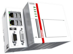
Beckhoff PLCs
Engineering Functions Supported
Other Supported Devices
B&R PLCs
Engineering Functions Supported
Other Supported Devices
Mitsubishi PLCs
Engineering Functions Supported
Other Supported Devices
Schnieder Electric PLCs
Engineering Functions Supported
Other Supported Devices
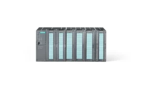
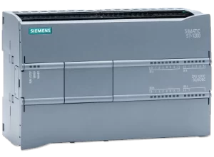
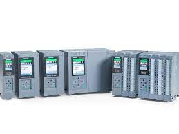
Siemens PLCs
Engineering Functions Supported
Other Supported Devices
Unitronics PLCs
Engineering Functions Supported
Other Supported Devices
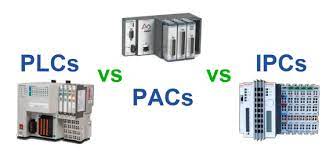
What are the differences?
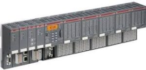
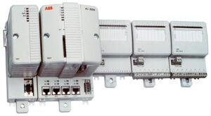
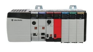
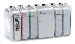
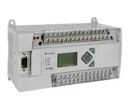
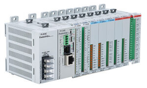
PLC (Programmable Logic Controller) and PAC (Programmable Automation Controller) are both devices used in industrial automation to control and manage various processes and machinery. While they share similarities, they also have distinct differences in terms of functionality, capabilities, and application focus.
PLC (Programmable Logic Controller):
- Functionality: PLCs are primarily designed for discrete control applications. They are well-suited for tasks involving binary operations, such as on/off control, sequencing, and logic operations. PLCs are often used in industries like manufacturing, automotive, and material handling.
- Programming: PLC programming is traditionally ladder logic-based, which is easy to understand and resembles electrical relay logic. PLCs use a scan cycle to execute the program repeatedly, ensuring real-time control.
- I/O Handling: PLCs excel at handling digital I/O (input/output) signals and are optimized for managing a large number of discrete devices, such as sensors and actuators.
- Scalability: PLCs can be easily expanded with additional I/O modules, making them suitable for applications where a large number of I/O points are needed.
PAC (Programmable Automation Controller):
- Functionality: PACs are designed for both discrete and process control applications. They can handle more complex control strategies and are suitable for applications involving both discrete and analog control, as well as motion control and advanced calculations.
- Programming: PAC programming often supports multiple programming languages, including ladder logic, structured text, and even high-level languages like C++. This makes PACs more flexible for complex control tasks.
- I/O Handling: PACs can handle both digital and analog I/O, making them suitable for a wider range of applications that involve both binary and continuous processes.
- Scalability: PACs are typically designed with more processing power, memory, and communication capabilities. They can handle larger and more complex applications, making them suitable for scalable and high-performance systems.
- Integration: PACs often offer better integration capabilities, enabling seamless communication with other devices and systems. They may include built-in communication interfaces like Ethernet, OPC UA, and industrial protocols.
- Advanced Control: PACs can execute complex control algorithms and calculations, making them suitable for applications with advanced motion control, robotics, and data analysis.
In summary, while both PLCs and PACs serve as automation controllers, the choice between them depends on the complexity of the application and the specific requirements. PLCs are typically more focused on discrete control tasks, while PACs offer greater flexibility, support for more programming languages, and the ability to handle both discrete and process control tasks, making them suitable for more diverse and complex industrial automation applications.
Data Aquisition, Instrumentation & Real Time Control with National Instruments
National Instruments
Elevating Real-Time Control and Data Acquisition: ASR - Engineering Harnesses LabVIEW's Power for Precision and Innovation
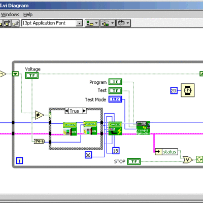
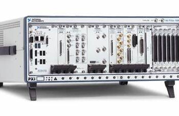
At ASR – Engineering, our team of engineers has been deeply engaged in harnessing the power of National Instruments LabVIEW for our real-time control and data acquisition endeavors. The remarkable capabilities of LabVIEW have enabled us to craft intricate systems that demand impeccable timing and precise data capture.
When we embark on a real-time control project, we seamlessly integrate LabVIEW’s real-time module into our workflow. This empowers us to design and execute intricate control algorithms within the LabVIEW ecosystem, ensuring they respond promptly to input signals and execute with the determinism required for applications like industrial automation. From orchestrating complex robotic motions to orchestrating critical process controls, LabVIEW’s real-time functionalities enable us to attain the heightened responsiveness our projects demand.
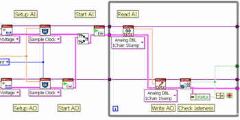
In the sphere of data acquisition, LabVIEW becomes our trusted ally, providing an expansive toolkit that streamlines the entire process. Through LabVIEW-compatible hardware, we seamlessly interface with diverse sensors and transducers, bridging the gap between the physical world and our software environment. Leveraging LabVIEW’s intuitive graphical programming interface, we effortlessly construct tailored data acquisition routines by dragging and dropping components. Signal conditioning, calibration, and synchronization mechanisms are seamlessly implemented to ensure accurate and dependable data collection across a spectrum of sources.
LabVIEW’s versatility shines brilliantly as we construct these systems. Be it a project centered around structural health monitoring, where we gather data from strain gauges mounted on a bridge, or any other venture, LabVIEW empowers us to visualize real-time strain variations, perform intricate analyses, and activate alerts when predetermined thresholds are surpassed — all achieved through an intuitive and user-friendly graphical interface.
Collaboration is further elevated through LabVIEW, allowing our team to collectively contribute to the same project. We share libraries, modules, and custom code seamlessly, not only expediting development but also ensuring consistency and coherence across diverse components.
In summary, at ASR – Engineering, our utilization of National Instruments LabVIEW for real-time control and data acquisition initiatives has propelled us into a realm of innovation and efficiency. We are not simply engineers; we are creators of ingenious solutions that drive progress across industries spanning manufacturing, aerospace, and beyond. LabVIEW has become an instrumental tool that empowers us to design, prototype, and deploy intricate systems with precision and excellence.
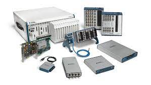
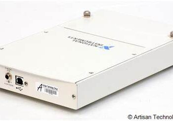
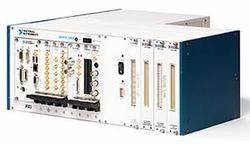
DAQ Hardware
What is DAQ?
DAQ stands for Data Acquisition. It refers to the process of collecting, measuring, and recording data from various physical phenomena or processes. In the context of industrial automation, scientific research, and engineering applications, DAQ involves the conversion of real-world analog signals into digital data that can be processed and analyzed by computers and software.
Here’s how DAQ is typically used:
- Sensor Interface: DAQ systems are equipped with hardware interfaces to connect a wide range of sensors and transducers. These sensors could measure physical quantities such as temperature, pressure, voltage, current, strain, acceleration, and more.
- Signal Conditioning: Before data is acquired, analog signals from sensors might require conditioning. This involves amplification, attenuation, filtering, or isolation to ensure that the signals are accurate, within a measurable range, and compatible with the DAQ hardware.
- Data Conversion: Analog signals are converted into digital data using analog-to-digital converters (ADCs). The ADC samples the analog signal at discrete intervals and quantizes the signal to obtain a digital representation.
- Data Processing: Once the data is digitized, it can be processed, analyzed, and visualized using software tools. This could involve performing calculations, filtering out noise, applying algorithms, and generating graphical representations.
- Data Storage: The acquired and processed data can be stored in various formats, such as databases, spreadsheets, or dedicated data storage systems. This allows for historical analysis, comparison, and trend identification.
- Control and Automation: In some cases, DAQ systems are used for control purposes. For instance, in a temperature control application, a DAQ system can continuously measure the temperature and adjust a heating or cooling system based on the acquired data.
- Monitoring and Testing: DAQ is crucial in monitoring and testing scenarios. Engineers use DAQ systems to validate and verify designs, troubleshoot issues, and ensure that systems operate within specified parameters.
- Research and Analysis: In scientific research, DAQ systems are used to gather experimental data for analysis. This could include studying the behavior of materials, biological processes, or physical phenomena.
- Quality Control: In manufacturing and production environments, DAQ is used to monitor and maintain product quality by collecting data from sensors and ensuring that processes are within predefined tolerances.
- Environmental Monitoring: DAQ systems are employed to monitor and record environmental data, such as air quality, water quality, and radiation levels.
DAQ systems can vary widely in complexity, ranging from simple setups with a few sensors to elaborate configurations involving multiple sensors, high-speed data acquisition, and real-time processing. They play a vital role in enabling informed decision-making, optimizing processes, and advancing scientific understanding across various fields.
How is DAQ Used?
Data Acquisition (DAQ) is a critical process in various fields of engineering and science, enabling the collection, measurement, and analysis of real-world data from physical phenomena or processes. DAQ systems consist of hardware components such as sensors, transducers, signal conditioning circuits, analog-to-digital converters (ADCs), and software interfaces that work together to acquire process, and present data for analysis. Here’s how DAQ is commonly used:
- Sensor Connection and Signal Conditioning:
- DAQ begins with the connection of sensors or transducers to the DAQ hardware. These sensors could measure parameters like temperature, pressure, voltage, current, strain, acceleration, etc.
- Signal conditioning is often applied to the sensor signals. This might involve amplification, filtering, and isolation to ensure that the signals are accurate, within a measurable range, and compatible with the DAQ hardware.
- Analog-to-Digital Conversion (ADC):
- Analog signals from sensors are converted into digital data using ADCs. The ADC samples the analog signal at discrete time intervals, quantizes the signal, and produces a digital representation that can be processed by computers.
- Data Acquisition Software:
- Specialized software, often provided by the DAQ system manufacturer or custom-developed, interfaces with the DAQ hardware to control the data acquisition process.
- The software allows users to set up parameters such as sampling rate, duration, and triggering conditions for data acquisition.
- Data Collection and Storage:
- During the data acquisition process, the software collects data points based on the specified parameters. These data points represent the digitized values of the measured physical quantities.
- The acquired data is stored in files, databases, or other storage mediums for further analysis.
- Real-Time Monitoring and Control:
- Many DAQ systems provide real-time monitoring capabilities, allowing users to visualize the acquired data as it is being collected. This can be useful for immediate feedback and troubleshooting.
- Data Analysis and Visualization:
- Acquired data is typically analyzed using specialized software tools, which can include mathematical algorithms, signal processing techniques, and statistical analysis.
- Data can be visualized through graphs, charts, histograms, and other graphical representations to provide insights into trends, patterns, anomalies, and relationships within the data.
- Reporting and Decision-Making:
- The results of data analysis are often used for informed decision-making. Engineers, scientists, and researchers can draw conclusions, make predictions, and optimize processes based on the insights gained from the collected data.
- Quality Control and Automation:
- In manufacturing and production environments, DAQ is used for quality control by monitoring and ensuring that products meet specified standards and tolerances.
- DAQ systems can also be integrated into automated processes to adjust parameters and optimize system performance in real time.
- Scientific Research and Experimentation:
- In research and experimentation, DAQ is used to gather empirical data for scientific investigations, allowing researchers to validate hypotheses, observe phenomena, and draw conclusions.
Overall, DAQ plays a crucial role in diverse industries, including manufacturing, automotive, aerospace, energy, environmental monitoring, healthcare, and scientific research, by enabling the precise measurement and analysis of physical phenomena and processes.
What is real time control & DAQ and where is it used?
Real-Time Control: Real-time control refers to the ability to execute control algorithms and respond to inputs within a precise and deterministic time frame. National Instruments provides real-time control solutions through their hardware platforms and LabVIEW Real-Time software. This technology allows engineers and scientists to develop control systems that require immediate and predictable responses, often in applications where timing and accuracy are critical.
Key features and applications of National Instruments’ real-time control technology include:
- Deterministic Execution: Real-time control systems ensure that control algorithms are executed within specified time intervals, guaranteeing timely and accurate responses to changing conditions.
- Industrial Automation: Real-time control is used in various industrial automation scenarios, such as robotics, motion control, and process control, where precision and synchronization are essential.
- Aerospace and Defense: Real-time control is employed in flight control systems, radar tracking, and other applications requiring instantaneous response to external inputs.
- Automotive Testing: Real-time control is used for testing and simulation in automotive research and development, including engine control and vehicle dynamics.
Data Acquisition (DAQ): Data Acquisition involves the process of measuring and collecting data from physical phenomena or processes. National Instruments offers DAQ hardware and software solutions that allow users to acquire, analyze, and present data from sensors, transducers, and other sources.
Key features and applications of National Instruments’ DAQ technology include:
- Sensor Interface: DAQ systems connect to a wide range of sensors and transducers to measure physical parameters such as temperature, pressure, voltage, and current.
- Signal Conditioning: DAQ systems often include signal conditioning capabilities to amplify, filter, or isolate sensor signals before data is acquired.
- Testing and Measurement: DAQ is extensively used in test and measurement applications, including product testing, quality control, and scientific research.
- Structural Health Monitoring: DAQ technology is employed in monitoring the structural integrity of bridges, buildings, and other infrastructure.
- Environmental Monitoring: DAQ systems are used to gather data from environmental sensors for applications such as climate research and pollution monitoring.
Overall, National Instruments’ real-time control and DAQ technologies find applications in various industries where precise control, measurement, and data analysis are essential. These technologies empower engineers and researchers to design and optimize systems, improve efficiency, and gain insights from data.
Realtime Control & DAQ
A closer look at the completed projects carried out by ASR - Engineering Inc. using National Instruments products:
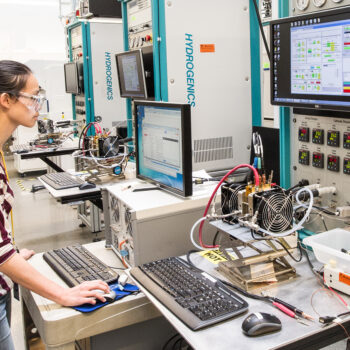
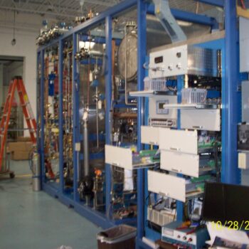
1. Fuel Cell Test Stand: ASR – Engineering Inc. successfully designed and implemented a state-of-the-art Fuel Cell Test Stand utilizing cutting-edge National Instruments products. This innovative test stand allowed for the comprehensive evaluation and analysis of fuel cell performance and efficiency. By seamlessly integrating NI hardware and software solutions, we achieved real-time monitoring and control of critical parameters, enabling precise data acquisition and analysis.
Key Accomplishments:
- Developed a custom LabVIEW-based software interface for real-time control and data acquisition of the fuel cell test stand.
- Utilized National Instruments data acquisition modules to seamlessly interface with a wide array of sensors, collecting critical data such as voltage, current, temperature, and pressure.
- Enabled automated testing procedures and dynamic control algorithms, enhancing efficiency and accuracy in fuel cell performance testing.
- Conducted extensive analysis of fuel cell efficiency, degradation, and response to varying load conditions, facilitating data-driven decision-making for fuel cell optimization.
2. Automotive Components Destructive Test Analysis: ASR – Engineering Inc. undertook a comprehensive project involving the destructive testing and analysis of automotive components, leveraging National Instruments products to drive insightful results. Our team seamlessly integrated NI hardware to facilitate real-time data collection during destructive tests, enabling engineers to assess component integrity and failure mechanisms.
Key Accomplishments:
- Employed National Instruments data acquisition systems to capture data during destructive tests, including load, stress, strain, and displacement measurements.
- Developed LabVIEW applications to visualize and analyze stress-strain curves, failure points, and material properties, aiding in understanding component behavior under extreme conditions.
- Enabled high-speed data acquisition and synchronization, offering a detailed perspective on component failure modes, and facilitating enhanced design and material selection strategies.
- Delivered actionable insights to clients, empowering them to optimize component design, durability, and overall performance, resulting in safer and more reliable automotive systems.
3. Nuclear Industry Sliding Stem Valve Testing: ASR – Engineering Inc. executed a comprehensive testing project focused on sliding stem valves for the nuclear industry. By leveraging National Instruments products, we ensured accurate and reliable testing of these critical components, adhering to stringent industry standards and safety protocols.
Key Accomplishments:
- Utilized National Instruments data acquisition and control solutions to create a robust testing environment for sliding stem valves.
- Developed LabVIEW-based control systems to simulate operating conditions and assess valve performance under various scenarios.
- Integrated high-precision sensors and measurement devices to capture data during valve testing, ensuring compliance with rigorous nuclear industry requirements.
- Provided clients with detailed performance reports, including valve response, leakage rates, and durability assessments, contributing to enhanced safety and operational efficiency within the nuclear sector.
These projects exemplify ASR – Engineering Inc.’s proficiency in utilizing National Instruments products to drive innovation, efficiency, and precision across a range of complex engineering challenges. Our commitment to leveraging cutting-edge technology ensures that clients receive tailored solutions that elevate performance, optimize processes, and foster a deeper understanding of their respective fields.
